Simulate an oscilloscope in Python: AWG, RC filter, 10x probe and a decoded waveform block
By Alex Hernandez · · 14 min read
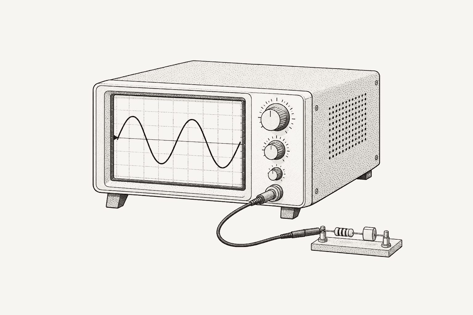
To simulate an oscilloscope in Python, wire a simulated function generator through an RC filter into a simulated scope, then drive it as you would hardware: set the trigger, send :DIGitize, read :WAVeform:DATA? as an IEEE 488.2 block and convert its 16-bit codes to volts with the preamble. This guide builds that capture and checks it against 1/(2πRC).
EdgeSim is the open-source bench simulator from Galois Labs: simulated instruments wired into simulated benches that PyVISA scripts, pytest, galois-edge and AI agents can't tell from real hardware. The bench here is its awg_rc_scope example: a function generator, a 1 kΩ and 100 nF low-pass, and scope channel 1 behind a 10x probe. Every command and output below ran against EdgeSim 0.2.0 and PyVISA 1.16.2 on Linux. EdgeSim's open-source release, with the edgesim package and its example benches, is coming soon. Sources are Keysight's InfiniiVision 3000 X-Series programmer's guide and EdgeSim's contracts/semantics.md, section 6. This guide owns trigger, fetch, decode and the corner check, and SCPI instrument automation with Python covers error queues and *OPC?.
How is a simulated scope capture built?
A net in EdgeSim carries a description of a signal, not samples. The function generator's net holds a 1 kHz sine, the RC low-pass adds a lowpass1 at 1,591.5 Hz to its output net, and the probe divides by ten at the scope port. Nothing is sampled until the scope asks.
The scope profile, galois_sim-scope-1, carries a sim.acquire block in its :WAVeform:DATA? leaf. The leaf runs at the bench's current virtual time; :DIGitize only advances the clock by 10 ms. Five stages turn the net into bytes:
| Stage | What the simulator does | What you set |
|---|---|---|
| Front end | Net signal at the port, divided by the probe; highpass1(10 Hz) when coupling is AC; lowpass1 at the port's 100 MHz bandwidth | Probe on the bench edge; :CHANnel1:COUPling |
| Sample | 2,000 samples at fs = 100 / timebase scale, twice the 1,000 returned | :TIMebase:SCALe |
| Trigger and window | Schmitt trigger: arms below the level minus 2% of the record's span, fires at the first sample at or above it (rising); 500 samples before and 500 after; auto-trigger at the record start when no edge is found | :TRIGger:EDGE:SOURce, :LEVel, :SLOPe |
| Quantize | Signed 16-bit codes, round(v / (4 × scale) × 32768), clamped | :CHANnel1:SCALe, :CHANnel1:OFFSet |
| Frame | An IEEE 488.2 block, #42000: 2,000 bytes and a line feed; the preamble comes from the same state | :WAVeform:PREamble?, :WAVeform:DATA? |
One code is therefore 4 × scale / 32768 volts at the scope input: 6.1 µV at 0.05 V/div. The profile follows Keysight's InfiniiVision transfer: a WORD block and a ten-field preamble.
How do I wire the AWG, filter and scope?
The bench is a topology file, the same file the Galois cloud editor draws, with an ext.sim bag on each node and edge. This excerpt is the shipped awg_rc_scope.bench.yaml:
nodes:
  - id: dut-main
    kind: dut
    label: RC low-pass
    position: {x: 0, y: 0}
    size: {width: 240, height: 150}
    ext:
      sim:
        model: edgesim.duts.passive:RCLowPass
        params: {r_ohm: 1000.0, c_f: 1.0e-7, input: fn-signal-in, output: fn-signal-out}
  # ... fn-signal-in and fn-signal-out function ports elided
  - id: inst-awg-sim1
    kind: instrument
    label: awg
    position: {x: -320, y: 45}
    instrumentId: sim-awg-1
    instrumentModel: SIM-AWG-1
    functionRole: awg
    ext: {sim: {profile: galois_sim-awg-1, state: {source.frequency: 1000.0, source.amplitude: 2.0}}}
  # ... inst-scope-sim1 elided
edges:
  - {id: e-awg-in, source: inst-awg-sim1, target: fn-signal-in, sourceHandle: right, targetHandle: left,
     label: awg, direction: forward, animated: true, ext: {sim: {sourcePort: OUT1}}}
  - {id: e-out-scope, source: fn-signal-out, target: inst-scope-sim1, sourceHandle: right, targetHandle: left,
     label: scope, direction: forward, animated: true, ext: {sim: {targetPort: CH1, probe: {atten: 10.0, r_ohm: 1.0e7, c_pf: 12.0}}}}
The DUT is the filter. RCLowPass binds fn-signal-in and fn-signal-out: a series 1 kΩ between the two nets, and a lowpass1 at 1/(2π·R·C) on the output. The capacitor is open at DC, so DC passes at unity.
Nets follow the edges. The AWG's OUT1 drives the filter input, the filter drives its output net and CH1 loads it. A net may have one driver; a second is E-NET-MULTIDRIVER.
The probe sits on the edge. atten: 10.0 divides the signal at the scope port, and r_ohm replaces the port's 1 MΩ as the load on the filter output.
Validate before running. A clean file prints nothing and exits 0:
edgesim validate awg_rc_scope.bench.yaml
echo "exit $?"exit 0PyVISA opens the bench in process through the @edgesim backend, and each instrument gets the next socket-style address, 5025 and up; the EdgeSim announcement lists the other ways in:
import pyvisa

rm = pyvisa.ResourceManager("awg_rc_scope.bench.yaml@edgesim")   # the bench opens in this process
print(rm.list_resources())
for address in rm.list_resources():
    inst = rm.open_resource(address, read_termination="\n", write_termination="\n")
print(inst.query("*IDN?"))('TCPIP0::127.0.0.1::5025::SOCKET', 'TCPIP0::127.0.0.1::5026::SOCKET')
GALOIS,SIM-AWG-1,SIM00001,edgesim-1
GALOIS,SIM-SCOPE-1,SIM00001,edgesim-1Later scripts open the bench through one helper. Save it, with the scope.py and measure.py modules shown below, in a bench/ folder beside the scripts, and run them from that folder:
import pyvisa


def open_rig(bench: str):
    """Open a bench file in process; return (awg, scope), the first and last instruments in the file."""
    rm = pyvisa.ResourceManager(f"{bench}@edgesim")
    sessions = [
        rm.open_resource(address, read_termination="\n", write_termination="\n")
        for address in rm.list_resources()
    ]
    return sessions[0], sessions[-1]
How do I trigger and fetch a waveform?
A capture is three requests after the trigger setup: :DIGitize, :WAVeform:PREamble? and :WAVeform:DATA?. The AWG starts at its bench-file setting, 1 kHz and 2 Vpp. The filter leaves 1.69 Vpp, the probe divides it to 0.17 Vpp, and :CHANnel1:SCALe 0.05 gives 0.4 V full scale at the BNC, which holds the 0.085 V peak with room to spare.
import numpy as np

from bench.rig import open_rig

awg, scope = open_rig("awg_rc_scope.bench.yaml")
awg.write(":OUTPut1:STATe ON")              # 1 kHz, 2 Vpp from the bench file
scope.write(":CHANnel1:SCALe 0.05")         # 0.4 V full scale at the BNC
scope.write(":TRIGger:EDGE:SOURce CHANnel1")
scope.write(":TRIGger:EDGE:LEVel 0")        # volts at the scope input
scope.write(":TRIGger:EDGE:SLOPe POSitive")
scope.write(":DIGitize")

print(scope.query(":WAVeform:PREamble?"))
codes = scope.query_binary_values(
    ":WAVeform:DATA?", datatype="h", is_big_endian=False, container=np.array
)
print(len(codes), codes.min(), codes.max())+1.000000E+00,+0.000000E+00,+1.000000E+03,+1.000000E+00,+1.000000E-05,-5.000000E-03,+0.000000E+00,+6.103516E-06,+0.000000E+00,+0.000000E+00
1000 -13868 14127The preamble reads: WORD format, normal type, 1,000 points, count 1, 10 µs between samples, the first sample 5 ms before the trigger, and 6.1 µV per code.
Read the block by its length, not by its terminator. A binary payload can contain a 0x0A byte, the line feed that read_termination="\n" treats as the end of a message. At 100 Hz on a 10 ms/div timebase this capture does (split_block is defined in the next section):
from bench.rig import open_rig
from bench.scope import split_block

awg, scope = open_rig("awg_rc_scope.bench.yaml")
awg.write(":SOURce1:FREQuency 100")
awg.write(":OUTPut1:STATe ON")
scope.write(":CHANnel1:SCALe 0.05;:TIMebase:SCALe 0.01;:DIGitize")

scope.write(":WAVeform:DATA?")
raw = scope.read_raw()                 # read_termination="\n" ends the read at the first 0x0A byte
print(len(raw), raw[:6])
try:
    split_block(raw)
except ValueError as exc:
    print(exc)

scope.read_termination = None          # without a termination character the read counts the block
scope.write(":WAVeform:DATA?")
raw = scope.read_raw()
print(len(raw), raw[:6], len(split_block(raw)))51 b'#42000'
block says 2000 bytes, got 45
2007 b'#42000' 2000The first read stopped after 51 bytes with no error from the instrument. query_binary_values reads the header and then exactly that many bytes, so a 0x0A inside the data is data.
How do I decode the block into volts?
Keysight's programmer's guide gives the conversion as "voltage = [(data value - yreference) * yincrement] + yorigin", and the time axis the same way from the x fields. The ten-field preamble reads format, type, points, count, x increment, x origin, x reference, y increment, y origin, y reference. In the simulator y_origin is the channel offset and y_reference is 0 for signed codes.
Source: Keysight, InfiniiVision 3000 X-Series Programmer's Guide, February 2024, read 2026-10-06
Two details of the block matter on real scopes. The length field. A definite-length block is #, one digit for how many length digits follow, the length, then the payload. EdgeSim frames 2,000 bytes as #42000 and Keysight's example for 1,000 bytes is #800001000, so a decoder reads the digit count and never assumes it. Byte order. Of :WAVeform:BYTeorder, Keysight says "The default setting is MSBFirst." A real InfiniiVision scope needs LSBFirst before this guide's is_big_endian=False read is right. The simulated scope already sends little-endian words, has no such command and answers -113, "Undefined header", so keep setup lines per model, as swap.py does below.
from dataclasses import dataclass

import numpy as np


@dataclass(frozen=True)
class Capture:
    t: np.ndarray        # seconds, 0 at the trigger point
    v: np.ndarray        # volts at the probe tip
    preamble: tuple      # the ten preamble fields, as floats


def split_block(raw: bytes) -> bytes:
    """Payload of an IEEE 488.2 definite-length block: #<n><n digits of byte count><payload>."""
    if raw[:1] != b"#" or not raw[1:2].isdigit() or raw[1:2] == b"0":
        raise ValueError(f"not a definite-length block: {raw[:12]!r}")
    digits = int(raw[1:2])
    size = int(raw[2 : 2 + digits])
    payload = raw[2 + digits : 2 + digits + size]
    if len(payload) != size:
        raise ValueError(f"block says {size} bytes, got {len(payload)}")
    return payload


def to_volts(codes: np.ndarray, preamble: tuple, probe: float = 1.0) -> Capture:
    """v = (code - y_reference) * y_increment + y_origin; t = (i - x_reference) * x_increment + x_origin."""
    fmt, _, points, _, x_inc, x_org, x_ref, y_inc, y_org, y_ref = preamble
    if int(fmt) != 1:
        raise ValueError(f"preamble format {int(fmt)} is not WORD")
    if len(codes) != int(points):
        raise ValueError(f"preamble says {int(points)} points, block holds {len(codes)}")
    v = ((codes - y_ref) * y_inc + y_org) * probe
    t = (np.arange(len(codes)) - x_ref) * x_inc + x_org
    return Capture(t, v, preamble)


def capture(scope, probe: float = 1.0, digitize: str = ":DIGitize") -> Capture:
    """Digitize one record, fetch it as a WORD block and decode it."""
    scope.write(digitize)
    preamble = tuple(scope.query_ascii_values(":WAVeform:PREamble?"))
    codes = scope.query_binary_values(
        ":WAVeform:DATA?", datatype="h", is_big_endian=False, container=np.array
    )
    return to_volts(codes, preamble, probe)
to_volts checks the format and point count first, and probe=10.0 multiplies scope-input volts back to the probe tip. Decode the capture from fetch.py and compare it with the filter's response at 1 kHz, 1/√(1 + (1000/1591.5)²) = 0.8467. fit_sine is defined in the next section:
import numpy as np

from bench.measure import FC_HZ, SETTLE_S, fit_sine
from bench.rig import open_rig
from bench.scope import capture

awg, scope = open_rig("awg_rc_scope.bench.yaml")
awg.write(":OUTPut1:STATe ON")                  # 1 kHz, 2 Vpp from the bench file
scope.write(":CHANnel1:SCALe 0.05")

cap = capture(scope, probe=10.0)
_, _, points, _, x_inc, x_org, _, y_inc, _, _ = cap.preamble
print(f"points {points:.0f}, x_increment {x_inc:.3g} s, x_origin {x_org:.3g} s, y_increment {y_inc:.6g} V")
print(f"window {cap.t[0] * 1e3:+.2f} to {cap.t[-1] * 1e3:+.2f} ms around the trigger")

amp, _ = fit_sine(cap, 1000.0, skip_s=SETTLE_S)
print(f"fitted amplitude {amp:.4f} V at the probe tip, expected {1 / np.sqrt(1 + (1000.0 / FC_HZ) ** 2):.4f} V")
print(f"one code is {y_inc * 10.0 * 1e6:.1f} uV at the probe tip")points 1000, x_increment 1e-05 s, x_origin -0.005 s, y_increment 6.10352e-06 V
window -5.00 to +4.99 ms around the trigger
fitted amplitude 0.8468 V at the probe tip, expected 0.8467 V
one code is 61.0 uV at the probe tipWhere is the trigger point?
The time axis is zero at the trigger, so sample 500 is the trigger sample and a rising trigger puts the level between samples 499 and 500.
from bench.rig import open_rig
from bench.scope import capture

awg, scope = open_rig("awg_rc_scope.bench.yaml")
awg.write(":OUTPut1:STATe ON")
scope.write(":CHANnel1:SCALe 0.05")

print(f"{'slope':<9} {'level_V':>7} {'v[499]':>8} {'v[500]':>8} {'t[500]':>8}")
for slope, level in (("POSitive", 0.0), ("NEGative", 0.0), ("POSitive", 0.05), ("POSitive", 0.5)):
    scope.write(f":TRIGger:EDGE:SLOPe {slope}")
    scope.write(f":TRIGger:EDGE:LEVel {level}")      # volts at the scope input, after the probe
    cap = capture(scope, probe=10.0)
print(f"{slope:<9} {level:7.2f} {cap.v[499]:+8.4f} {cap.v[500]:+8.4f} {cap.t[500] * 1e3:+8.3f}ms")slope level_V v[499] v[500] t[500]
POSitive 0.00 -0.0233 +0.0300 +0.000ms
NEGative 0.00 +0.0233 -0.0300 +0.000ms
POSitive 0.05 +0.4788 +0.5217 +0.000ms
POSitive 0.50 -0.4731 -0.4282 +0.000msRows 1 and 2 cross zero in opposite directions, so each slope puts the window at a different point of the cycle. In row 3 sample 500 is the first at or above 0.5 V at the tip, and the trigger does not interpolate, so it is accurate to one sample, 10 µs here. Row 4 asks for an edge the signal never makes, 5 V at the tip, so the scope auto-triggers at the record start and still returns a block.
What does the console's scope screen show?
edgesim tui awg_rc_scope.bench.yaml opens this bench in the terminal console. Its scope screen streams what the front end hands the ADC: the port's reading with the probe applied, then AC coupling and bandwidth. That is the signal :WAVeform:DATA? samples, so its amplitude, offset and trigger agree with the fetch above. The header counts the clock and names the run state. r stops and runs the trace, SINGLE holds the record :DIGitize then :WAVeform:DATA? returns, code for code, m steps the memory depth through 1k, 10k and 100k points, and the display rolls from 50 ms/div. In the clip the timebase turns from 1 ms/div to 250 µs/div, one command per frame, and the trigger holds the edge:
With the clock running, the timebase glides from 1.000 ms/div to 250.0 µs/div at one command per frame, and the triggered 1 kHz trace widens from ten cycles to two and a half.
How do I check the corner against 1/(2πRC)?
For R = 1 kΩ and C = 100 nF, fc = 1 / (2π × 1000 × 10⁻⁷) = 1 / (6.2832 × 10⁻⁴) = 1,591.5 Hz. At fc the gain is 1/√(1 + 1) = 0.7071, which is -3.01 dB. The test sweeps the AWG, captures at each point, reduces each capture to one gain and compares it with 1/√(1 + (f/fc)²).
A least-squares sine fit with a DC term beats half of max - min for reducing a capture to an amplitude, because the start-up transient stretches the first cycles of a record, and two choices keep it honest. Twenty cycles at 50 samples per cycle: set the timebase to 2 / f seconds per division, so the 10 divisions hold 20 cycles and fs = 100 / scale is 50 f. Skip five time constants: leave out the first 5RC = 0.5 ms of each record. The simulator starts each filter as if its input had been constant at the record's first sample (semantics.md, §6.4.1); a real RC settles over a similar span after a frequency change.
import numpy as np

from bench.scope import Capture, capture

R_OHM, C_F = 1000.0, 1.0e-7                 # the RC low-pass in awg_rc_scope.bench.yaml
FC_HZ = 1 / (2 * np.pi * R_OHM * C_F)       # 1591.5 Hz
SETTLE_S = 5 * R_OHM * C_F                  # five time constants, 0.5 ms


def fit_sine(cap: Capture, freq_hz: float, skip_s: float = 0.0) -> tuple[float, float]:
    """Peak amplitude and DC level of the sine at freq_hz, by least squares.

    Samples in the first skip_s seconds of the record are left out of the fit."""
    keep = cap.t - cap.t[0] >= skip_s
    t, v = cap.t[keep], cap.v[keep]
    basis = np.column_stack([np.sin(2 * np.pi * freq_hz * t), np.cos(2 * np.pi * freq_hz * t), np.ones_like(t)])
    (s, c, dc), *_ = np.linalg.lstsq(basis, v, rcond=None)
    return float(np.hypot(s, c)), float(dc)


def gain_at(awg, scope, freq_hz: float, vpp_in: float = 2.0, probe: float = 10.0, **kw) -> float:
    """Set the AWG, give the scope 20 cycles at 50 samples per cycle, return |Vout| / |Vin|."""
    awg.write(f":SOURce1:FREQuency {freq_hz}")
    scope.write(f":TIMebase:SCALe {2 / freq_hz}")   # 10 divisions = 20 cycles; fs = 100 / scale
    amp, _ = fit_sine(capture(scope, probe=probe, **kw), freq_hz, skip_s=SETTLE_S)
    return 2 * amp / vpp_in


def corner_hz(freqs, gains, drop_db: float = 3.0103) -> float:
    """Frequency where the gain crosses -drop_db, interpolating dB against log frequency."""
    db = 20 * np.log10(np.asarray(gains))
return float(np.exp(np.interp(-drop_db, db[::-1], np.log(freqs)[::-1])))import numpy as np
from bench.measure import FC_HZ, corner_hz, gain_at
from bench.rig import open_rig
awg, scope = open_rig("awg_rc_scope.bench.yaml")
awg.write(":SOURce1:VOLTage 2.0") # 2 Vpp
awg.write(":OUTPut1:STATe ON")
scope.write(":CHANnel1:SCALe 0.05") # 0.4 V full scale at the BNC
freqs = [100, 250, 500, 1000, 1400, 1800, 2500, 5000, 10000, 20000]
gains = [gain_at(awg, scope, f) for f in freqs]
print(f"{'f_Hz':>6} {'gain':>7} {'dB':>7} {'expected':>9} {'err_%':>6}")
for f, g in zip(freqs, gains):
expected = 1 / np.sqrt(1 + (f / FC_HZ) ** 2)
print(f"{f:6d} {g:7.4f} {20 * np.log10(g):7.2f} {expected:9.4f} {100 * (g / expected - 1):+6.2f}")
corner = corner_hz(freqs, gains)
print(f"-3 dB at {corner:.1f} Hz; 1/(2*pi*R*C) = {FC_HZ:.1f} Hz ({100 * (corner / FC_HZ - 1):+.2f}%)")
at_fc = gain_at(awg, scope, FC_HZ)
print(f"gain at {FC_HZ:.1f} Hz: {at_fc:.4f} ({20 * np.log10(at_fc):.2f} dB); 1/sqrt(2) = {1 / np.sqrt(2):.4f} (-3.01 dB)") f_Hz gain dB expected err_%
100 0.9985 -0.01 0.9980 +0.04
250 0.9884 -0.10 0.9879 +0.05
500 0.9546 -0.40 0.9540 +0.06
1000 0.8472 -1.44 0.8467 +0.05
1400 0.7513 -2.48 0.7508 +0.05
1800 0.6628 -3.57 0.6624 +0.06
2500 0.5373 -5.40 0.5370 +0.06
5000 0.3035 -10.36 0.3033 +0.05
10000 0.1573 -16.07 0.1572 +0.07
20000 0.0794 -22.01 0.0793 +0.07
-3 dB at 1580.8 Hz; 1/(2*pi*R*C) = 1591.5 Hz (-0.68%)
gain at 1591.5 Hz: 0.7075 (-3.01 dB); 1/sqrt(2) = 0.7071 (-3.01 dB)Every point is within 0.07% of the formula. The interpolated corner is 0.68% low because dB against log frequency bends between 1,400 and 1,800 Hz, a property of the grid and not of the scope; a measurement at fc reads 0.7075, or -3.01 dB.
What do coupling and probe attenuation change?
Coupling. AC coupling puts highpass1(10 Hz) ahead of the ADC. With 1 V of AWG offset under the sine:
from bench.measure import fit_sine, SETTLE_S
from bench.rig import open_rig
from bench.scope import capture

awg, scope = open_rig("awg_rc_scope.bench.yaml")
awg.write(":SOURce1:VOLTage:OFFSet 1.0")           # 1 V of DC under the sine
awg.write(":OUTPut1:STATe ON")
scope.write(":CHANnel1:SCALe 0.2")

print(f"{'coupling':<8} {'f_Hz':>6} {'dc_V':>8} {'amp_V':>8}")
for f in (1000, 10):
    awg.write(f":SOURce1:FREQuency {f}")
    scope.write(f":TIMebase:SCALe {2 / f}")
    for coupling in ("DC", "AC"):
        scope.write(f":CHANnel1:COUPling {coupling}")
        amp, dc = fit_sine(capture(scope, probe=10.0), f, skip_s=SETTLE_S)
print(f"{coupling:<8} {f:6d} {dc:+8.4f} {amp:8.4f}")coupling f_Hz dc_V amp_V
DC 1000 +0.9999 0.8472
AC 1000 -0.0056 0.8466
DC 10 +0.9999 0.9999
AC 10 +0.0000 0.6636DC coupling keeps the 1 V; AC coupling removes it, leaving -5.6 mV, and the 1 kHz amplitude agrees within 0.1%. At 10 Hz, the high-pass corner, the AC-coupled amplitude is 0.664 of the DC-coupled one, against 0.707 for an analog single pole. The gap is the discrete filter: with a = exp(-2π·10/fs) (semantics.md, OP_HIGHPASS1), its gain at 10 Hz is 0.6636 at fs = 500 Hz, as measured, and 0.7027 at fs = 5 kHz. Measure low frequencies with AC coupling off, or sample them faster.
Probe attenuation. The probe sits on the bench edge, so the preamble describes volts at the scope input. The reference scope profile has no probe-ratio setting; the decoder takes the factor as probe. The same capture, decoded both ways at two vertical scales:
from bench.rig import open_rig
from bench.scope import capture

awg, scope = open_rig("awg_rc_scope.bench.yaml")
awg.write(":OUTPut1:STATe ON")
for scale in (1.0, 0.05):
    scope.write(f":CHANnel1:SCALe {scale}")
    at_bnc, at_tip = capture(scope, probe=1.0), capture(scope, probe=10.0)
    lsb = at_bnc.preamble[7]
    print(f"{scale:5.2f} V/div: LSB {lsb * 1e6:6.1f} uV at the BNC, "
f"vpp {at_bnc.v.max() - at_bnc.v.min():.3f} V (probe=1), {at_tip.v.max() - at_tip.v.min():.3f} V (probe=10)") 1.00 V/div: LSB 122.1 uV at the BNC, vpp 0.171 V (probe=1), 1.708 V (probe=10)
0.05 V/div: LSB 6.1 uV at the BNC, vpp 0.171 V (probe=1), 1.709 V (probe=10)Forgetting the factor reads a tenth of the signal. Choose the vertical scale for the signal at the scope input, not at the tip: at 1 V/div the 0.17 Vpp spans about 1,400 codes, at 0.05 V/div about 28,000. The trigger level follows the same rule. On a real scope, Keysight says :CHANnel<n>:PROBe "does not change the actual input sensitivity of the oscilloscope. It changes the reference constants for scaling the display factors, for making automatic measurements, and for setting trigger levels." Check whether your scope's preamble already reports probe-tip volts; if it does, set probe to 1.0.
Source: Keysight, InfiniiVision 3000 X-Series Programmer's Guide, February 2024, read 2026-10-06
The probe edge also carries c_pf, and a cable can carry a length and an impedance. Transient probe and cable coupling is in build: probe capacitance and cable length will shape the edge the scope sees, from keys already in the bench file, so rise-time and ringing captures run on the bench you have.
How do I daisy-chain another stage?
Two RC DUTs cannot connect output to input directly. Add a second RCLowPass, dut-rc2, to awg_rc_scope.bench.yaml and wire fn-signal-out straight to its input port fn-in-2, and validation fails:
E-NET-UNSUPPORTED /nodes/0/ext/sim DUT 'dut-main' filters signals into net 'net-1' ('fn-signal-in' -> 'fn-signal-out'), but another series element (dut-rc2:fn-in-2->fn-out-2) connects to itThe diagnostic matches the physics: two passive stages with no buffer load each other, and the corner moves. An instrument between the stages breaks the loading, so the chain is AWG, RC 1, a unity-gain buffer, RC 2, scope. The buffer is a 37-line profile, saved in profiles/ next to the bench file, which is on the search path:
# yaml-language-server: $schema=profile-v2.schema.json
schema_version: 2

instrument:
  manufacturer: Example
  model: BUF-1
  class: test
  description: Unity-gain buffer between two stages

identity:
  query: "*IDN?"
  patterns: ["EXAMPLE,BUF-1,.*"]

state:
  output:
    enabled: {type: bool, initial: true}

ports:
  IN:  {dir: in,  medium: voltage, z_ohm: 1.0e+6}
  OUT: {dir: out, medium: voltage, z_ohm: 50.0}

commands:
  output:
    state:
      type: property
      getter: ":OUTPut:STATe?"
      setter: ":OUTPut:STATe {state}"
      params:
        state: {type: enum, options: ["ON", "OFF"], map: {"ON": 1, "OFF": 0}}
      returns: {type: bool}
      writes: [output.enabled]
      reads: [output.enabled]

sim:
  idn: "EXAMPLE,BUF-1,SN0001,rev1"
  ports:
    OUT: "port('IN').v if state.output.enabled else open()"
rc_rc_scope.bench.yaml is the shipped file with a second DUT, the buffer node and three edges in place of e-out-scope. It validates clean:
nodes:
  # dut-main, fn-signal-in and fn-signal-out stay as shipped; add the second stage after them
  - id: dut-rc2
    kind: dut
    label: RC stage 2
    position: {x: 0, y: 220}
    size: {width: 240, height: 150}
    ext:
      sim:
        model: edgesim.duts.passive:RCLowPass
        params: {r_ohm: 1000.0, c_f: 1.0e-7, input: fn-in-2, output: fn-out-2}
  - {id: fn-in-2,  kind: function, label: In 2,  position: {x: 24, y: 264}, parentId: dut-rc2, functionRole: signal-in,
     ext: {sim: {port: {dir: in,  medium: voltage}}}}
  - {id: fn-out-2, kind: function, label: Out 2, position: {x: 24, y: 304}, parentId: dut-rc2, functionRole: signal-out,
     ext: {sim: {port: {dir: out, medium: voltage}}}}
  # inst-awg-sim1 stays; the buffer goes between it and inst-scope-sim1
  - id: inst-buf
    kind: instrument
    label: buffer
    position: {x: 40, y: 150}
    instrumentId: buf-1
    instrumentModel: BUF-1
    functionRole: buffer
    ext: {sim: {profile: example_buf-1}}
edges:
  # e-awg-in stays; e-out-scope is replaced by these three
  - {id: e-rc1-buf, source: fn-signal-out, target: inst-buf, ext: {sim: {targetPort: IN}}}
  - {id: e-buf-rc2, source: inst-buf, target: fn-in-2, ext: {sim: {sourcePort: OUT}}}
  - {id: e-rc2-scope, source: fn-out-2, target: inst-scope-sim1,
     ext: {sim: {targetPort: CH1, probe: {atten: 10.0, r_ohm: 1.0e7, c_pf: 12.0}}}}
The sweep reuses gain_at. Two equal poles give 0.5 at fc, and the -3 dB point moves to fc × √(√2 - 1) = 1,591.5 × 0.6436 = 1,024.3 Hz:
import numpy as np

from bench.measure import FC_HZ, corner_hz, gain_at
from bench.rig import open_rig

awg, scope = open_rig("rc_rc_scope.bench.yaml")      # AWG, buffer and scope; the rig takes first and last
awg.write(":OUTPut1:STATe ON")
scope.write(":CHANnel1:SCALe 0.05")

freqs = [100, 250, 500, 1000, 1400, 1800, 2500, 5000, 10000, 20000]
gains = [gain_at(awg, scope, f) for f in freqs]
at_fc = gain_at(awg, scope, FC_HZ)
print(f"gain at {FC_HZ:.1f} Hz: {at_fc:.4f} ({20 * np.log10(at_fc):.2f} dB); two poles predict 0.5000 (-6.02 dB)")
f3, expected = corner_hz(freqs, gains), FC_HZ * np.sqrt(np.sqrt(2) - 1)
print(f"-3 dB at {f3:.1f} Hz; fc * sqrt(sqrt(2) - 1) = {expected:.1f} Hz ({100 * (f3 / expected - 1):+.2f}%)")gain at 1591.5 Hz: 0.5000 (-6.02 dB); two poles predict 0.5000 (-6.02 dB)
-3 dB at 1019.7 Hz; fc * sqrt(sqrt(2) - 1) = 1024.3 Hz (-0.45%)The scope's net holds RC 1's filter inside a nested term and RC 2's as the outer op, so the scope samples the whole chain on demand.
Does the same capture come back identical?
Yes, which lets a capture sit in a regression test. The bytes are a pure function of the bench revision, the virtual time and the seed: the same virtual time returns the same block, a later one returns another, and a second process returns the same bytes:
import hashlib

import edgesim
from edgesim import Advance, Scpi

AWG, SCOPE = "sim-awg-1", "sim-scope-1"
digest = lambda b: hashlib.sha256(b).hexdigest()[:16]

with edgesim.open_bench("awg_rc_scope.bench.yaml") as world:
    world.scpi(AWG, ":OUTPut1:STATe ON")
    world.scpi(SCOPE, ":CHANnel1:SCALe 0.05;:DIGitize")
    (t,) = world.step(Scpi(SCOPE, b":WAVeform:DATA?"))
    again = world.scpi(SCOPE, b":WAVeform:DATA?")
    print("fetch 1  ", digest(t.observation.response), len(t.observation.response), "bytes at", t.t_virtual_ns, "ns")
    print("fetch 2  ", digest(again), "same virtual time")
    print("data_ref ", dict(t.observation.data_ref))
    world.step(Advance(0.00025))                 # a quarter of a 1 kHz cycle later
    later = world.scpi(SCOPE, b":WAVeform:DATA?")
print("later ", digest(later), "after Advance(0.25 ms)")fetch 1 0fa777a42766614e 2007 bytes at 10000000 ns
fetch 2 0fa777a42766614e same virtual time
data_ref {'kind': 'regenerable', 'revision': 2, 't_trig_ns': 15090000, 'window': {'pre': 500, 'post': 500, 'fs_hz': 100000.0}, 'seed': 7, 'nbytes': 2006}
later 535ca16efc32c8f9 after Advance(0.25 ms)Run the script twice in separate processes and fetch 1 prints 0fa777a42766614e both times. The trace records a capture as a data_ref recipe, not as 2 kB of bytes: the trigger at 15.09 ms, a window of 500 samples either side at 100 kS/s, and the bench seed, 7.
Does the decoder carry to a Keysight scope?
EdgeSim ships a converted Keysight InfiniiVision 3000 X-Series profile. awg_rc_dsox.bench.yaml is awg_rc_scope.bench.yaml with the scope node's profile: set to keysight_infiniivision_3000_x-series, and the decode and the gain measurement carry over unchanged. Two things differ in what you send: setup lines, and :DIGitize CHANnel1, the form that profile declares. The converted profile free-runs with no trigger block, so the trigger behavior above belongs to galois_sim-scope-1.
import pyvisa

from bench.measure import gain_at

# Per model: bench file, setup lines sent once, and the :DIGitize form. The gain path needs nothing else.
SCOPES = {
    "galois_sim-scope-1": ("awg_rc_scope.bench.yaml", (), ":DIGitize"),
    "keysight_infiniivision_3000_x-series": (
        "awg_rc_dsox.bench.yaml",
        (":WAVeform:FORMat WORD", ":WAVeform:BYTeorder LSBFirst", ":WAVeform:UNSigned 0"),
        ":DIGitize CHANnel1",
    ),
}
for profile, (bench, setup, digitize) in SCOPES.items():
    rm = pyvisa.ResourceManager(f"{bench}@edgesim")
    awg, scope = (rm.open_resource(a, read_termination="\n", write_termination="\n") for a in rm.list_resources())
    awg.write(":OUTPut1:STATe ON")
    for command in (":CHANnel1:SCALe 0.05", *setup):
        scope.write(command)
    g = [gain_at(awg, scope, f, digitize=digitize) for f in (1000, 1591.5494)]
    idn = scope.query("*IDN?").split(",")
print(f"{idn[0]} {idn[1]}: gain {g[0]:.4f} at 1 kHz, {g[1]:.4f} at fc; errors: {scope.query('SYSTem:ERRor?')}")GALOIS SIM-SCOPE-1: gain 0.8472 at 1 kHz, 0.7075 at fc; errors: 0,"No error"
KEYSIGHT TECHNOLOGIES DSOX3034T: gain 0.8472 at 1 kHz, 0.7075 at fc; errors: 0,"No error"No physical scope ran this guide, so make your first real capture the check: compare its gain at fc with 0.7071 and settle byte order and probe factor there.
How do I run this in Galois with Évariste?
Galois is agent-driven test engineering for hardware teams: agents generate tests and instrument drivers, run them on real benches through the open-source galois-edge daemon, and turn the results into reports and a shared engineering record. EdgeSim plugs into galois-edge as an instrument backend, so Évariste, the agent in the Galois platform, works the virtual bench with the tools it uses on a real one.
Open Évariste from the app sidebar (Ctrl+Shift+E) beside your project and state the test with its limits:
Create a sequence for the function generator at TCPIP0::127.0.0.1::5025::SOCKET, called awg, and the scope at TCPIP0::127.0.0.1::5026::SOCKET, called scope. CH1 is behind a 10x probe, so report volts at the probe tip. At 100 Hz, 1,591.5 Hz and 10 kHz: set the AWG to a 2 Vpp sine, set the timebase to show 20 cycles, trigger on a rising edge at 0 V on CH1, digitize and fetch the waveform, skipping the first 0.5 ms of each record. Report the gain at each frequency, flag any gain more than 2% from 1/√(1 + (f/fc)²) for a 1 kΩ and 100 nF low-pass, and flag the frequency nearest -3 dB against 1/(2πRC). Leave the AWG output off at the end.
Draft. Évariste reads the two profiles and drafts a sequence of named profile commands, with the timebase set from 2 / f at each frequency:
name: "RC low-pass gain at 100 Hz, 1.59 kHz and 10 kHz"
steps:
  # setup elided: AWG 2 Vpp sine and output on; CH1 at 0.05 V/div; rising edge at 0 V on CH1
  - name: "AWG 1591.5 Hz"
    type: action
    config:
      instrument_id: "awg"
      command_name: "set_frequency"
      parameters: { frequency: "1591.5" }

  - name: "Timebase for 20 cycles"
    type: action
    config:
      instrument_id: "scope"
      command_name: "timebase_scale"
      parameters: { scale: "0.0012567" }

  - name: "Digitize"
    type: action
    config:
      instrument_id: "scope"
      command_name: "digitize"

  - name: "Waveform CH1 at 1591.5 Hz"
    type: measure
    config:
      instrument_id: "scope"
      command_name: "waveform_data"
      unit: "V"

  # the same four steps at 100 Hz and 10 kHz

  - name: "AWG output off"
    type: action
    config:
      instrument_id: "awg"
      command_name: "output_enable"
      parameters: { state: "OFF" }
Review and approve. A draft does not run until you approve it. Check the timebase at each frequency (20 ms/div at 100 Hz, 1.2567 ms/div at 1,591.5 Hz, 0.2 ms/div at 10 kHz), the AWG amplitude, the trigger level, the 10x probe factor and 0.5 ms skip in the analysis, and the output-off step. How to review an AI-generated test plan lists more. Every change, in conversation or in the sequence builder, is a new version with a diff.
Run on the virtual bench. Set SIM_MODE=true and SIM_BENCH to the bench file in the galois-edge daemon's environment. The two simulated instruments appear in "List connected instruments" at TCPIP0::127.0.0.1::5025::SOCKET (function generator) and ...::5026::SOCKET (scope), beside any real ones. SIM_MARK_INSTRUMENTS=true adds is_simulated to the listing, and a trace written with TRACE_DIR set records provenance: sim, so a rehearsal can be told from a bench run. The daemon decodes each block with the profile's preamble map, the formula to_volts applies.
Results. Each step records its command, raw response, waveform, instrument, operator and timestamps. The results table lists the gain at each frequency, marks any row more than 2% from the formula and marks the row nearest -3 dB, which at these three frequencies is 1,591.5 Hz. "Generate a test report from the last run" produces a PDF or HTML report you can edit and share to Slack.
Real scope. Bind a real DSOX3000 in place of the simulated scope and Évariste retargets the sequence as a new version with its own diff and approval. The trace marks each step sim or real, and you can ask the report to say which bench produced each row.
Your job is the objective, the limits, the review and the approval, and with real hardware the probe, its compensation and the grounding. The block parser, decode, timebase arithmetic, fit and report script are no longer yours to write or maintain.
| Step | Code path (this guide) | Galois with Évariste |
|---|---|---|
| Bench | awg_rc_scope.bench.yaml, edgesim validate | The same file, loaded by galois-edge with SIM_MODE and SIM_BENCH |
| Define and drive | sweep.py: :DIGitize and :WAVeform:DATA? per frequency | Plain-English objective; profile commands digitize and waveform_data |
| Decode | to_volts(): (code - y_reference) * y_increment + y_origin | The daemon decodes with the profile's preamble map |
| Review and run | Code review, then python sweep.py | Draft reviewed, versioned, approved; run through galois-edge |
| Record and report | A printed table; your own script | Per-step waveform, raw I/O, operator, timestamps; generated PDF or HTML report |
| Reduce and interpret | fit_sine() and corner_hz(), then compare with 1/√(1 + (f/fc)²) yourself | Évariste computes gain per frequency and flags the row nearest -3 dB and gains off the formula |
| Real scope | Change setup lines and probe | Bind the real profile; the trace marks each step sim or real |
When is plain code enough?
For one engineer with one scope, bench/ from this guide is enough: a bench file, a decoder, a fit and a sweep, run in CI with no instrument. Galois earns its place when several people share benches, when the sequence needs review and versions, and when the run needs a record and a report.
A simulated scope proves your decode, timebase arithmetic, trigger logic and limits before the board exists. Probe compensation, ground lead, noise floor and the real ADC wait for the bench, so a pass rehearses the decode and the limits and says nothing about the hardware. The same fetch-and-decode pattern runs through post-silicon validation, EMC pre-compliance and the optical bench guide. For a PyVISA-only comparison, see Galois and PyVISA.
SMU IV sweep simulation is next: compliance, sweeps and the buffer on a simulated source-measure unit.
Frequently asked questions
- How do I simulate an oscilloscope in Python?
- Wire a simulated function generator through a filter into a simulated scope in an EdgeSim bench file, open it with pyvisa.ResourceManager('awg_rc_scope.bench.yaml@edgesim'), and drive the scope with :DIGitize, :WAVeform:PREamble? and :WAVeform:DATA?. The scope returns an IEEE 488.2 block of 16-bit codes, so the decoder you write against it reads volts with the preamble, and the same decoder reads a real scope's block once you settle byte order and probe factor.
- How do I decode an oscilloscope waveform block in Python?
- Read the block with PyVISA's query_binary_values (datatype h; little-endian on EdgeSim's scope, and on a Keysight scope once :WAVeform:BYTeorder LSBFirst is set), then apply Keysight's formula, volts = (code - y_reference) * y_increment + y_origin, with the y fields taken from the ten-field :WAVeform:PREamble? reply. Time is (index - x_reference) * x_increment + x_origin.
- Why does read_raw return a short waveform block?
- A VISA read stops at the termination character when read_termination is set, and a binary payload can contain a 0x0A byte. The read ends there and the block is shorter than its header says. Use query_binary_values, which reads the header and then exactly that many bytes, or clear read_termination for the block read.
- How do I find the corner frequency of an RC low-pass with a scope?
- Compute fc = 1/(2πRC), 1,591.5 Hz for 1 kΩ and 100 nF, where the gain is 1/√2 = 0.7071 (-3.01 dB). Then sweep the source frequency, capture 20 cycles at each point, fit the amplitude, take gain as output over input, and interpolate the -3.01 dB crossing in dB against log frequency.
- Do I multiply by the probe attenuation when I decode a waveform?
- It depends on who applied it. In EdgeSim the probe divides the signal at the scope port, so the preamble describes volts at the scope input and you multiply by 10 for a 10x probe. A real scope with :CHANnel<n>:PROBe set changes its scaling constants, so check whether its preamble already reports probe-tip volts before you multiply.
Bring Galois to your bench.
The daemon is Apache-2.0, free forever. Enterprise runs in your cloud or on-prem.