Photonics test automation with Python and SCPI: swept IL, PDL and return loss
By Alex Hernandez · · 14 min read
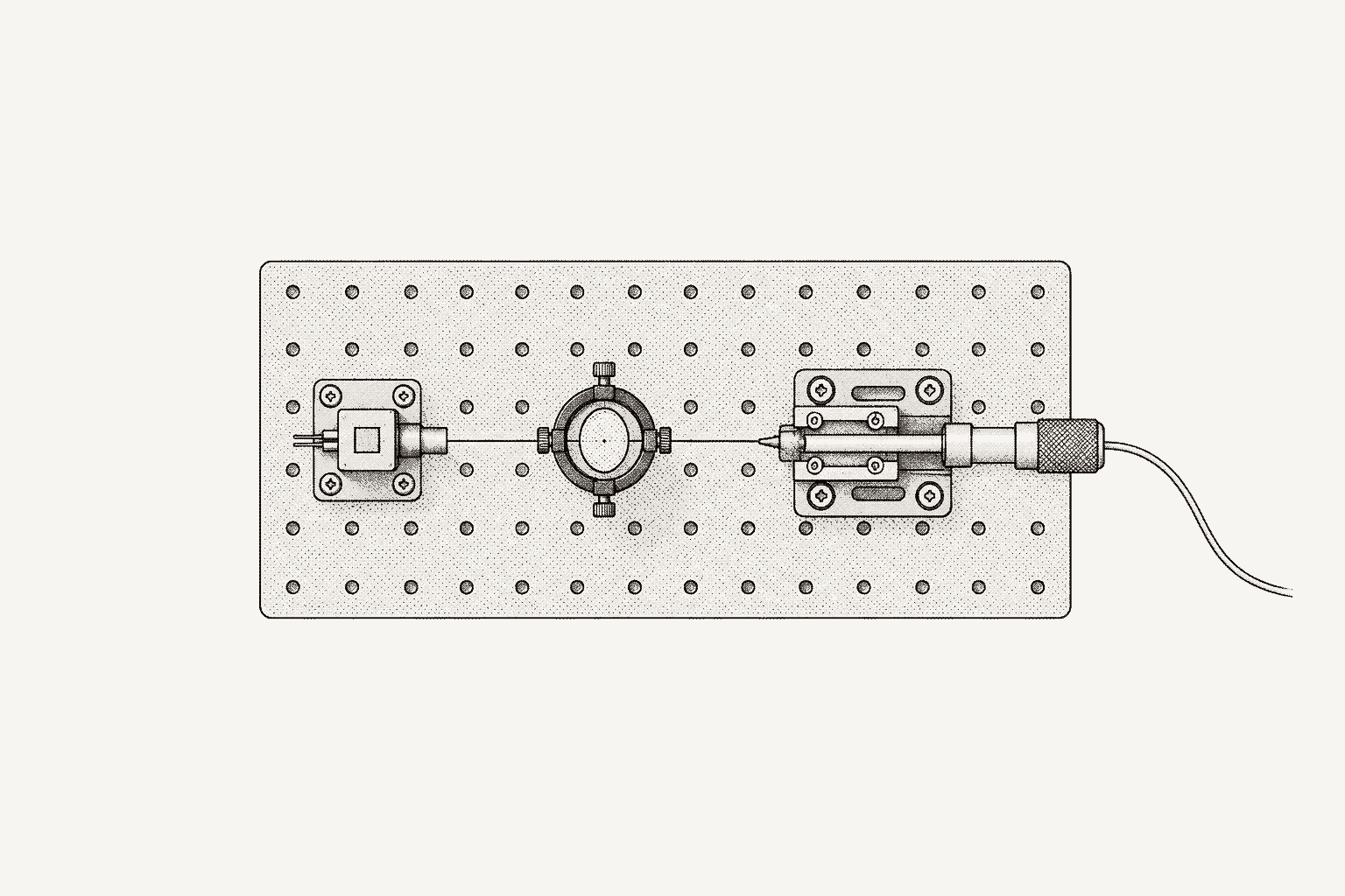
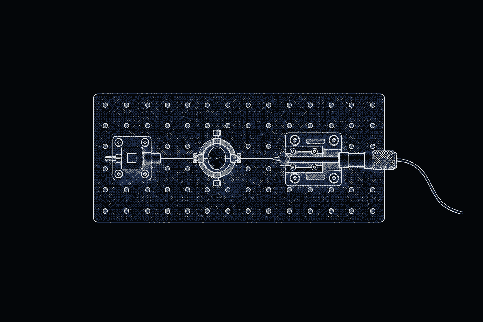
Photonics test automation means scripting the optical bench: a tunable laser sweeps wavelength, a power meter samples on the laser's step trigger, and Python turns a reference scan and a device scan into insertion loss. Polarization-dependent loss, return loss, switches, attenuators and OSA traces follow the same pattern, with PyVISA carrying the SCPI.
This guide builds each measurement on a Keysight 8164B Lightwave Measurement System, a mainframe with a back-loaded tunable laser in slot 0 and modules in slots 1 to 4, plus a Yokogawa AQ6374E optical spectrum analyzer. Every command comes from the 8163A/B, 8164A/B and 8166A/B programming guide (Edition 2.1, October 2020) or Yokogawa's AQ6374E remote control manual, and the code targets PyVISA 1.16. Other vendors name their commands differently; the structure carries over. For PyVISA basics, start with SCPI instrument automation with Python.
Which instruments does a photonics test bench automate?
A passive-component bench, for a splitter, filter, connector or photonic integrated circuit, chains a source, the device and a receiver, with routing and conditioning in between. Slot numbers below are examples.
| Instrument | Role in the test | Example commands |
|---|---|---|
| Tunable laser source | Sets wavelength and power; sweeps and emits a trigger per step | SOUR0:WAV 1550NM, SOUR0:WAV:SWE:MODE CONT |
| Optical power meter | Measures power; logs one sample per trigger | READ1:CHAN1:POW?, SENS1:CHAN1:FUNC:STAT LOGG,STAR |
| Return loss module | Measures light reflected back toward the source | READ2:RET? |
| Optical switch | Routes each device port to one meter | ROUT3:CHAN1 A,2 |
| Variable optical attenuator | Sets power levels; its shutter blocks the path | INP4:ATT 10DB, OUTP4:STAT OFF |
| Polarization controller | Sets the input state of polarization for PDL | Instrument-specific |
| Optical spectrum analyzer | Measures power against wavelength at a set resolution | :TRAC:Y? TRA (AQ6374E) |
The 8164B addresses modules by slot (SOUR0, SENS1, ROUT3) and channel; a dual power sensor's second input is CHAN2.
How do I control a tunable laser and power meter from Python?
The 8164B speaks GPIB, and mainframes from serial number DE48202000 on add LAN: VXI-11, a raw socket on port 5025 and Telnet on port 5024. Keysight recommends sockets for applications and puts VXI-11 at about 50 percent slower. On a socket every command must end in a newline, which write_termination adds.
import pyvisa

rm = pyvisa.ResourceManager()
lw = rm.open_resource(
    "TCPIP0::192.168.1.60::5025::SOCKET",  # or GPIB0::20::INSTR
    read_termination="\n",
    write_termination="\n",
    timeout=10_000,
)
print(lw.query("*IDN?"))  # the mainframe only
for slot in range(5):     # 8164B slots 0-4; slot 0 holds the back-loaded laser
    if int(lw.query(f":SLOT{slot}:EMPT?")) == 0:  # 0: module present
        print(slot, lw.query(f":SLOT{slot}:IDN?"))

lw.write("*CLS")
lw.write("SOUR0:WAV 1550NM")
lw.write("SOUR0:POW 0DBM")
lw.write("SENS1:CHAN1:POW:WAV 1550NM")  # selects the meter's responsivity correction
lw.write("SENS1:CHAN1:POW:UNIT 0")      # 0: dBm, 1: W
lw.write("SENS1:CHAN1:POW:ATIM 100MS")
lw.write("SOUR0:POW:STAT 1")            # laser on: light leaves the front panel
lw.query("*OPC?")
print(float(lw.query("READ1:CHAN1:POW?")), "dBm")
lw.write("SOUR0:POW:STAT 0")
Four details in this script carry into everything after it.
*IDN?names the mainframe, not the modules. Its manufacturer field reads Keysight Technologies, Agilent Technologies or HEWLETT-PACKARD, by production date. Each module answers:SLOT[n]:IDN?with its own model, serial and firmware date; record those.- Wavelengths are in meters. A wavelength sent without a unit suffix is read as meters, and
SOUR0:WAV?answers in meters, such as+1.5672030E-006.SOUR0:WAV? MINandMAXreturn the module's programmable limits, set for each unit at factory calibration. - The meter's wavelength is a setting.
SENS1:CHAN1:POW:WAVselects the responsivity correction; it measures nothing. Match it to the laser for absolute readings. - Zero before low-power work.
SENS1:CORR:COLL:ZEROzeros the meter's electrical offsets, andSENS1:CORR:COLL:ZERO?returns 0 when the zero succeeded. Run it with the laser off and no light at the input.
How do I measure insertion loss across a wavelength sweep?
Insertion loss (IL) is the power lost through the device: IL(λ) = −10·log₁₀(P_device(λ) / P_reference(λ)) in dB, where the reference is the same path with the device removed. Getting both curves at fine wavelength resolution is the automation problem.
Stepped or continuous sweep?
A stepped measurement sets a wavelength, waits for the laser to settle, reads the meter and repeats: fine for a handful of wavelengths, thousands of round trips for a passband at picometer steps. In a continuous sweep, the laser tunes at constant speed and emits a trigger at the end of each step, the meter takes one sample per trigger, and the laser records the wavelength at which each trigger fired. Keysight calls the last part lambda logging.
The programming guide sets the limits. The trigger frequency, sweep speed divided by step, may not exceed 40 kHz, or 1 MHz on the 81602A, 81606A, 81607A, 81608A and 81960A. A sweep allows at most 100,001 triggers, and the start wavelength must be below the stop. Lambda logging adds three prerequisites: continuous sweep mode, the laser's output trigger set to step finished, and amplitude modulation off (or set to coherence control). If one is missing, the sweep reports inconsistent parameters and lambda logging switches off. SOUR0:WAV:SWE:CHEC? names the broken rule beforehand.
Trigger the power meter from the laser
import time

import numpy as np

LASER, METER = 0, 1  # 8164B slots: back-loaded tunable laser, power meter


def read_blocks(lw, max_query: str, block_query: str, count: int, datatype: str) -> np.ndarray:
    """Read `count` values in chunks no larger than the instrument's transfer limit."""
    size = int(lw.query(max_query))
    chunks = [
        lw.query_binary_values(
            f"{block_query}{offset},{min(size, count - offset)}",
            datatype=datatype,    # "d": 8-byte double, "f": 4-byte float
            is_big_endian=False,  # Intel byte order
            container=np.array,
        )
        for offset in range(0, count, size)
    ]
    return np.concatenate(chunks)


def swept_scan(lw, start_nm, stop_nm, step_pm, speed_nm_s, avg_time="100US", range_dbm=0):
    """One continuous sweep: laser-logged wavelengths in nm, meter readings in W."""
    for command in (
        "*CLS",
        "TRIG:CONF LOOP",                  # output trigger re-enters as an input trigger
        f"TRIG{LASER}:INP IGN",            # the laser ignores its own looped-back triggers
        f"SOUR{LASER}:AM:STAT OFF",        # lambda logging needs modulation off
        f"SOUR{LASER}:WAV:SWE:MODE CONT",
        f"SOUR{LASER}:WAV:SWE:STAR {start_nm}NM",
        f"SOUR{LASER}:WAV:SWE:STOP {stop_nm}NM",
        f"SOUR{LASER}:WAV:SWE:STEP {step_pm}PM",
        f"SOUR{LASER}:WAV:SWE:SPE {speed_nm_s}NM/S",
        f"SOUR{LASER}:WAV:SWE:CYCL 1",
        f"TRIG{LASER}:OUTP STF",           # one trigger at the end of every step
        f"SOUR{LASER}:WAV:SWE:LLOG 1",
    ):
        lw.write(command)
    check = lw.query(f"SOUR{LASER}:WAV:SWE:CHEC?")
    if "OK" not in check:
        raise RuntimeError(f"sweep rejected: {check}")
    points = int(lw.query(f"SOUR{LASER}:WAV:SWE:EXP?"))

    for command in (
        f"SENS{METER}:CHAN1:FUNC:STAT LOGG,STOP",
        f"SENS{METER}:CHAN1:POW:UNIT 1",   # W, so noise near zero stays a number
        f"SENS{METER}:CHAN1:POW:WAV {(start_nm + stop_nm) / 2}NM",
        f"SENS{METER}:CHAN1:POW:RANG:AUTO 0",
        f"SENS{METER}:CHAN1:POW:RANG {range_dbm}DBM",
        f"TRIG{METER}:CHAN1:INP SME",      # each incoming trigger takes one sample
        f"SENS{METER}:CHAN1:FUNC:PAR:LOGG {points},{avg_time}",
        f"SOUR{LASER}:POW:STAT 1",         # laser on
        f"SENS{METER}:CHAN1:FUNC:STAT LOGG,STAR",  # arm the meter before the sweep starts
        f"SOUR{LASER}:WAV:SWE STAR",
    ):
        lw.write(command)

    deadline = time.monotonic() + (stop_nm - start_nm) / speed_nm_s + 30
    while "COMPLETE" not in lw.query(f"SENS{METER}:CHAN1:FUNC:STAT?"):
        if time.monotonic() > deadline:
            raise TimeoutError("logging incomplete: check the trigger setup")
        time.sleep(0.2)
    while int(lw.query(f"SOUR{LASER}:WAV:SWE?")):  # +1 while the sweep runs
        time.sleep(0.1)

    logged = int(lw.query(f"SOUR{LASER}:READ:POIN? LLOG"))
    if logged != points:
        raise RuntimeError(f"{points} triggers expected, {logged} wavelengths logged")
    wavelength_m = read_blocks(
        lw, f"SOUR{LASER}:READ:DATA:MAXB?", f"SOUR{LASER}:READ:DATA:BLOC? LLOG,", points, "d"
    )
    power_w = read_blocks(
        lw, f"SENS{METER}:CHAN1:FUNC:RES:MAXB?", f"SENS{METER}:CHAN1:FUNC:RES:BLOC? ", points, "f"
    )
    wavelength_nm = wavelength_m * 1e9  # meters, like every other wavelength the guide returns
    if abs(wavelength_nm[0] - start_nm) > 1 or abs(wavelength_nm[-1] - stop_nm) > 1:
        raise RuntimeError("logged wavelengths do not span the sweep: check their unit")
    return wavelength_nm, power_w
Each block answers a rule from the guide.
- No trigger cable.
TRIG:CONF LOOPfeeds the mainframe's output trigger back to its input, so the laser's step-finished trigger reaches the meter internally. - Points come from the laser.
SOUR0:WAV:SWE:EXP?returns the sweep's trigger count, which is the sample count the meter must log. A 1525 to 1565 nm sweep at 5 pm is 8,001 points: 8 seconds at 5 nm/s, triggers at 1 kHz. - Averaging must fit the step. The step interval is step divided by speed, 1 ms here. Choose a supported averaging time shorter than that, so every trigger finds the meter ready.
- Fix the range. The guide warns that autoranging while other commands reach a meter "has lead to timing conflicts in some configurations," so set a range at or above the highest expected power. For a deep stopband, repeat the sweep at a lower range and splice where both are valid.
- Arm first. A trigger that arrives while
FUNC:STATis executing makes the first logged value invalid, so the meter is armed before the sweep starts. - Binary blocks, little-endian. Logged wavelengths arrive as 8-byte doubles and powers as 4-byte floats, both in Intel byte order inside IEEE 488.2 blocks.
query_binary_values()parses the header; state the data type and byte order yourself.MAXB?gives the largest single transfer, hence the chunked reads. The guide gives no unit for logged wavelengths; the code assumes meters and checks that they span the sweep. - Log in watts. At the noise floor a reading can be zero or negative, and the guide notes the meter cannot convert a negative value to dBm. Take the logarithm in Python.
Normalize against a reference scan
import numpy as np


def on_grid(scan, grid_nm):
    """Lambda-logged wavelengths are not exactly equally spaced: resample onto a shared grid."""
    wavelength_nm, power_w = scan
    return np.interp(grid_nm, wavelength_nm, power_w)


def insertion_loss_db(reference, dut, start_nm, stop_nm, step_pm):
    points = round((stop_nm - start_nm) * 1_000 / step_pm) + 1
    grid_nm = np.linspace(start_nm, stop_nm, points)
    p_ref, p_dut = on_grid(reference, grid_nm), on_grid(dut, grid_nm)
    valid = (p_ref > 0) & (p_dut > 0)  # readings at the noise floor can be zero or negative
    il_db = np.full(points, np.nan)
    il_db[valid] = -10 * np.log10(p_dut[valid] / p_ref[valid])
    return grid_nm, il_db


def passband(grid_nm, il_db, low_nm, high_nm):
    band = (grid_nm >= low_nm) & (grid_nm <= high_nm) & np.isfinite(il_db)
    il, wl = il_db[band], grid_nm[band]
    return {
        "il_max_db": float(il.max()),
        "il_min_db": float(il.min()),
        "ripple_db": float(il.max() - il.min()),
        "worst_nm": float(wl[il.argmax()]),
}# lw: the 8164B session opened in connect.py
from bench.lightwave import swept_scan
from bench.loss import insertion_loss_db, passband
SWEEP = dict(start_nm=1525, stop_nm=1565, step_pm=5, speed_nm_s=5)
input("Connect the reference patch cords, then press Enter")
reference = swept_scan(lw, **SWEEP)
input("Insert the device, then press Enter")
device = swept_scan(lw, **SWEEP)
lw.write("SOUR0:POW:STAT 0")
grid_nm, il_db = insertion_loss_db(reference, device, 1525, 1565, 5)
print(passband(grid_nm, il_db, 1530, 1560))The reference scan carries the laser's power variation across the band, the patch cords' loss, and the meter's responsivity, which changes with wavelength while the correction stays fixed at one setting. Dividing the device scan by the reference cancels all three, provided both scans use identical sweep, range and averaging settings.
Resampling matters because the logged wavelengths are where the laser actually was at each trigger, not an exact grid. Keysight's own Lambda Scan functions also interpolate onto equally spaced points, and the guide notes the cost: linear interpolation acts like a low-pass filter and rounds off sharp peaks. Keep the raw arrays, and pick a grid no coarser than the logged spacing. Any drift between the two scans becomes insertion loss error, so record when each reference was taken.
How do I measure polarization-dependent loss?
Polarization-dependent loss (PDL) is the peak-to-peak variation in transmission over all input states of polarization: PDL = 10·log₁₀(T_max / T_min). Keysight's application note Measuring Polarization Dependent Loss of Passive Optical Components compares the two common methods.
Polarization scanning exposes the device to many states and records the extremes. It is simple, accurate and fairly insensitive to operating conditions, but slow over wavelength: the note's example, 2,000 points over 20 nm at 1.5 s each, takes about 50 minutes.
The Mueller method measures transmission at four defined states, for example linear horizontal (LHP), linear vertical (LVP), linear +45 degrees (L+45) and right-hand circular (RHC). From four reference and four device measurements it solves for the first row of the device's Mueller matrix, m₁₁ to m₁₄, and computes T_max and T_min analytically. Because only four states are needed, each can be a full continuous sweep, which makes it the fast choice for PDL against wavelength, though the note warns that it demands more care to reach high accuracy. For PDL at many wavelengths the note prefers a single-scan variant, where a polarization synthesizer switches states during one sweep; the four-sweep form below needs only a controller that can set four states.
import numpy as np

STATES = ("LHP", "LVP", "L+45", "RHC")  # linear 0, 90 and +45 degrees, right circular


def mueller_pdl(reference: dict, dut: dict) -> dict:
    """Each dict maps a state to power in W on one shared wavelength grid."""
    t = {state: dut[state] / reference[state] for state in STATES}
    m11 = (t["LHP"] + t["LVP"]) / 2
    m12 = (t["LHP"] - t["LVP"]) / 2
    m13 = t["L+45"] - m11
    m14 = t["RHC"] - m11
    spread = np.sqrt(m12**2 + m13**2 + m14**2)
    t_max, t_min = m11 + spread, m11 - spread
    return {
        "pdl_db": 10 * np.log10(t_max / t_min),
        "il_avg_db": -10 * np.log10(m11),  # m11: transmission for unpolarized light
        "il_max_db": -10 * np.log10(t_min),
        "il_min_db": -10 * np.log10(t_max),
}# lw: the 8164B session opened in connect.py
import numpy as np
from bench.lightwave import swept_scan
from bench.loss import on_grid
from bench.pdl import STATES, mueller_pdl
SWEEP = dict(start_nm=1525, stop_nm=1565, step_pm=5, speed_nm_s=5)
GRID_NM = np.linspace(1525, 1565, 8_001)
def set_state(state: str) -> None:
"""Drive your polarization controller to LHP, LVP, L+45 or RHC (see its manual)."""
raise NotImplementedError
def scan_states() -> dict:
powers = {}
for state in STATES:
set_state(state)
powers[state] = on_grid(swept_scan(lw, **SWEEP), GRID_NM)
return powers
input("Connect the reference path, then press Enter")
reference = scan_states()
input("Insert the device, then press Enter")
result = mueller_pdl(reference, scan_states())
lw.write("SOUR0:POW:STAT 0")
print(f"max PDL {np.nanmax(result['pdl_db']):.3f} dB")m11 is the device's transmission for unpolarized light, so −10·log₁₀(m11) is a polarization-averaged insertion loss. The note's warnings belong in the test procedure: reference and device measurements must run at the same wavelength and power, and the reference sweeps capture the polarization controller's own variation but not the detector's polarization-dependent responsivity, which cannot be calibrated out. For the scanning method, a source with a high degree of polarization is mandatory.
How do I measure return loss?
Return loss (RL) is the ratio, in dB, of the power sent into the device to the power reflected back; higher means less reflection. An 8164B return loss module is calibrated against two references, then reads RL directly.
# lw: the 8164B session opened in connect.py
RL = 2  # return loss module in slot 2, internal source 1 selected and on

lw.write(f"SENS{RL}:RET:CORR:REFL1 0.18DB")  # your reflector's return loss, for source 1
input("Connect the reference reflector, then press Enter")
lw.write(f"SENS{RL}:RET:CAL:COLL:REFL")
lw.query("*OPC?")
input("Connect the termination reference, then press Enter")
lw.write(f"SENS{RL}:RET:CAL:COLL:TERM")
lw.query("*OPC?")
input("Connect the device, then press Enter")
print(float(lw.query(f"READ{RL}:RET?")), "dB return loss")
The 0.18 dB is the guide's own example: Keysight's 81000BR reference reflector. Use the value for your reflector. The digit after REFL picks the source: 1 and 2 are the lower and upper internal sources, and 0, the default, is an external one. Both calibrations apply to the currently selected source, so a dual-wavelength module is calibrated once per source.
How do I automate optical switches and attenuators?
A switch module turns one meter into many by routing each output of a 1×N splitter or demultiplexer to it in turn. ROUT3:CHAN1 A,2 connects port A to port 2 on switch 1 of the module in slot 3. The guide warns that on switches with dependent connections, such as a 2×2, setting one route can change another, so query the route after setting it. Reference each port through the switch; every path has its own loss.
# lw: the 8164B session opened in connect.py
from bench.lightwave import swept_scan
from bench.loss import insertion_loss_db

SWEEP = dict(start_nm=1525, stop_nm=1565, step_pm=5, speed_nm_s=5)
PORTS = range(1, 5)  # a 1x4 device's outputs on switch ports 1-4


def route(port: int) -> None:
    lw.write(f"ROUT3:CHAN1 A,{port}")
    lw.query("*OPC?")


lw.write("INP4:WAV 1550NM")  # attenuator in slot 4: wavelength for its loss calibration
lw.write("INP4:ATT 10DB")
lw.write("OUTP4:STAT ON")    # open the attenuator's shutter

input("Connect the reference path through the switch, then press Enter")
references = {}
for port in PORTS:
    route(port)
    references[port] = swept_scan(lw, **SWEEP)
input("Insert the device, then press Enter")
il_by_port = {}
for port in PORTS:
    route(port)
    il_by_port[port] = insertion_loss_db(references[port], swept_scan(lw, **SWEEP), 1525, 1565, 5)
lw.write("SOUR0:POW:STAT 0")
The attenuator's INP[n]:WAV setting compensates for its filter's wavelength dependence. Its shutter, OUTP[n]:STAT OFF, blocks the path without switching off the laser.
How do I read an optical spectrum analyzer trace in Python?
A power meter integrates everything that reaches it; an optical spectrum analyzer (OSA) resolves power against wavelength, which suits checking a laser's wavelength and side modes, or a filter's shape under a broadband source. The AQ6374E offers GP-IB, a socket on port 10001 by default that requires an OPEN login (user name anonymous by default), and VXI-11, which skips the login. Yokogawa's manual includes a PyVISA sample program; this script follows it.
import time

import numpy as np
import pyvisa

rm = pyvisa.ResourceManager()
osa = rm.open_resource("TCPIP0::192.168.1.100::inst0::INSTR", timeout=30_000)

osa.write("*RST")
osa.write("CFORM1")                  # AQ637x command mode, as in Yokogawa's sample
osa.write(":SENS:WAV:CENT 1550NM")
osa.write(":SENS:WAV:SPAN 10NM")
osa.write(":SENS:BAND:RES 0.05NM")   # rounded to the nearest preset resolution
osa.write(":SENS:SENS MID")
osa.write(":SENS:SWE:POIN:AUTO ON")
osa.write(":INIT:SMOD 1")            # single sweep
osa.write("*CLS")
osa.write(":INIT")
while not int(osa.query(":STAT:OPER:EVEN?")) & 1:  # bit 0: sweep finished
    time.sleep(0.2)

wavelength_m = np.array(osa.query_ascii_values(":TRAC:X? TRA"))  # meters, always
level = np.array(osa.query_ascii_values(":TRAC:Y? TRA"))         # log values on a LOG scale
peak = level.argmax()
print(f"peak {wavelength_m[peak] * 1e9:.3f} nm at {level[peak]:.2f}")
From the manual, before you trust a trace:
:TRAC:X?returns wavelengths in meters even when the screen shows frequency, and:TRAC:Y?returns log values on a LOG level scale and linear values on a linear one.- Resolution snaps to a preset: 0.05, 0.1, 0.2, 0.5, 1, 2, 5 or 10 nm on the AQ6374E.
:FORM:DATA REAL,64switches trace queries from the default ASCII to binary; check the decoded values against one ASCII read before relying on them.- Built-in analysis runs on the instrument:
:CALC:CAT SWTH, then:CALC, then:CALC:DATA?returns mean wavelength and spectral width. :SENS:CORR:RVEL:MEDreferences wavelengths to air or vacuum. Confirm every instrument in a comparison uses the same one.
What belongs in an IL, PDL and RL test report?
A report someone can recompute months later carries the following.
| Record | Why it matters |
|---|---|
| Device part number, serial number and port | Ties each number to one unit and one optical path |
Mainframe *IDN? and every :SLOT[n]:IDN? | Names the modules, serials and firmware that measured |
| Sweep range, step, speed, averaging time, meter range, laser power | Reproduces the scan |
| Reference scan file, time and patch cords | Insertion loss is only as good as its reference |
| Raw wavelength and power arrays, reference and device | Lets anyone recompute with another grid or band |
| Air or vacuum wavelength reference for OSA data | Wavelengths on different references do not compare directly |
| IL maximum and minimum, ripple, PDL maximum, RL minimum, each with its limit and verdict | The result, with the criterion it was judged against |
| Calibration status of each instrument, from your calibration records | Shows the measurement chain was in tolerance |
For layout, the DVT test report template carries over to optical results, and hardware test traceability covers linking each number back to the requirement it verifies. For calibration, see calibration status in automated test records.
How to run swept IL, PDL and RL tests in Galois with Évariste
Évariste, the agent in the Galois platform, does the same work from a conversation: open it from the app sidebar (Ctrl+Shift+E) beside a project, and it reaches the bench through the galois-edge daemon. Here is the switched insertion loss test, switch_voa.py.
Driver. Ask "List connected instruments" to see what your team's edges reach. If the 8164B has no profile, upload its programming guide PDF and Évariste generates one in the final section's format. Check mnemonics, units, the dangerous flag on laser_on, how the logged data blocks are decoded, and the queries swept_scan() relies on:
commands:
  sweep_check:
    scpi: "SOUR0:WAV:SWE:CHEC?"
    type: query
    returns: { type: string }  # names the broken rule; OK when there is none
  sweep_points:
    scpi: "SOUR0:WAV:SWE:EXP?"
    type: query
    returns: { type: int }     # triggers in the sweep: 8,001 for 1525-1565 nm at 5 pm
  logged_points:
    scpi: "SOUR0:READ:POIN? LLOG"
    type: query
    returns: { type: int }     # wavelengths logged; must equal sweep_points
After your review, Évariste deploys it to the edge and binds it to the 8164B.
Objective. State the sweep with this guide's settings and guard limits:
On the 8164B, set the slot 4 attenuator to 10 dB at 1550 nm and open its shutter. For each of ports 1 to 4 on the slot 3 switch, sweep the slot 0 laser from 1525 to 1565 nm in 5 pm steps at 5 nm/s, with the slot 1 meter in watts at a fixed 0 dBm range and 100 µs averaging, logging one sample per step trigger. Fail a port if the sweep check is not OK or fewer than 8,001 wavelengths are logged. Laser off at the end.
For PDL, add the polarization controller and a sweep in each of its four states; for return loss, the slot 2 module and your reflector's value.
Review. Évariste drafts a sequence, and a draft cannot run until an engineer approves it. This guide is the checklist: averaging shorter than the 1 ms step; a fixed meter range; the trigger looped back, continuous mode and modulation off; the meter armed before the sweep; sweep_check reading OK and logged_points equal to 8,001; all four ports swept; the laser off at the end. How to review an AI-generated test plan covers the rest. Request changes in the conversation or the sequence builder; each change is a new version with a diff. Lock the approved version before the reference run, so the device run uses identical settings.
Run. Run the sequence twice: with the reference path through the switch, then with the device inserted and its serial entered. Leave the logging meter out of Monitor so no extra query reaches it mid-sweep. Sent from the conversation on its own, laser_on waits for your confirmation.
Results. Each run records every step: measured value, limits, pass or fail, raw command and response, instrument, operator, DUT serial and timestamps. Ask Évariste to compare the device run with its reference run port by port over 1530 to 1560 nm and report insertion loss and ripple, citing the steps. Check its figures against the recorded data. Judging them against your datasheet limits stays yours, because no step in the sequence carries those limits. "Diagnose high PDL readings" works the same way.
Report. "Generate an IL/RL report" builds a PDF or HTML report from LaTeX templates. Add the patch cords in the report editor and share it, to Slack for example.
You no longer write or maintain the session code, swept_scan() and its error handling, the per-port loops, the result logging or a report script. The objective, limits, review, approval, physical setup and laser safety stay yours. AI test automation for hardware covers the agent loop.
| Step | Code path (this guide) | Galois with Évariste |
|---|---|---|
| Find instruments | *IDN?, :SLOT[n]:IDN? | "List connected instruments" |
| Driver | SCPI strings in each script | Profile generated from the PDF, reviewed, deployed |
| Sweep and logging | swept_scan() | Steps drafted from your objective |
| Guard checks | Exceptions in swept_scan() | sweep_check and logged_points steps |
| Reference and device | input() between scans | Two runs of one locked version |
| Switch and attenuator | route(), INP4:ATT | Steps in the same sequence |
| PDL states | set_state(), yours to write | The controller's profile |
| Return loss | measure_rl.py | Reference measurements, then an RL step |
| OSA trace | osa_trace.py | Profile generated from the AQ6374E manual, then a trace step in the sequence |
| IL, PDL, verdicts | insertion_loss_db(), passband(), mueller_pdl() | Évariste compares the two runs; the verdict against datasheet limits is yours |
| Changes | Edit and commit the scripts | Versions with diffs, approved before running |
| Results | Arrays and printouts you store | Per-step record with raw command and response |
| Report | Your report script | "Generate an IL/RL report" |
When is plain PyVISA enough?
For one bench, one engineer and one device family, PyVISA plus functions like these is a complete solution: short scripts, every command visible, nothing between you and the programming guide. Keysight also offers its own route: for LabVIEW and VEE users, the guide recommends the 816x VXIplug&play instrument driver for logging functions, and its Lambda Scan functions wrap the sweep, logging and resampling shown here.
Scripts strain when several benches share instruments, when reference, settings and results must land in one record without copy-paste, or when another team needs the same measurement next quarter. The Galois and PyVISA comparison shows where that line falls.
Where does Galois fit on an optical bench?
Galois is agent-driven test engineering for hardware teams: agents generate tests and instrument drivers, run them on real benches through the open-source galois-edge daemon, and turn the results into reports and a shared engineering record.
Its instrument library lists 573 profiles from 135 manufacturers, photonics gear included: Quantifi Photonics tunable lasers, power meters, switches, attenuators, polarization controllers and OSAs, EXFO IQS modules, and the Yokogawa AQ6370 OSA. An instrument without a profile still takes raw SCPI through the daemon. A profile types its commands; for the 8164B setup above, one would start like this (profile reference):
instrument:
  manufacturer: "Keysight"
  model: "8164B"
  class: laser
  description: "Lightwave Measurement System: tunable laser in slot 0, power meter in slot 1"

identity:
  patterns:
    - ",8164B,"  # Keysight, Agilent or HEWLETT-PACKARD, by production date

interfaces:
  - type: gpib
  - type: ethernet
    port: 5025

settings:
  timeout_ms: 10000
  terminator: "\n"
  init_commands: ["SENS1:CHAN1:POW:UNIT 1"]
  cleanup_commands: ["SOUR0:POW:STAT 0"]  # laser off on disconnect

commands:
  set_wavelength:
    scpi: "SOUR0:WAV {wavelength}NM"
    type: write
    params:
      wavelength: { type: float, unit: nm }
  laser_on:
    scpi: "SOUR0:POW:STAT 1"
    type: write
    is_dangerous: true  # light leaves the front panel
  laser_off:
    scpi: "SOUR0:POW:STAT 0"
    type: write         # no flag: switching the laser off never waits on approval
  read_power:
    scpi: "READ1:CHAN1:POW?"
    type: query
    returns: { type: float, unit: W }
Writing it by hand is covered in adding a SCPI instrument profile; Évariste can also generate one from the programming guide PDF for you to review, the first step of the walkthrough above (see also the LabVIEW comparison). Declarative instrument drivers explains why the commands live in data rather than classes.
Once a profile matches, the daemon exposes the instrument as typed Model Context Protocol tools, with is_dangerous carried into the tool catalog so an agent and its operator can see which call turns the laser on. MCP for lab instruments explains how agents reach the instruments, and LLM instrument safety covers the guardrails around a call like that. To try the daemon on your own bench, start with the quickstart.
Frequently asked questions
- What is photonics test automation?
- It is scripting an optical test bench so measurements run without manual steps: a tunable laser sweeps wavelength, power meters sample on the laser's triggers, switches route the device's ports, and software computes insertion loss, polarization-dependent loss and return loss against limits, then stores the raw data and settings with the result.
- How do you measure insertion loss over wavelength?
- Sweep a tunable laser through the reference path without the device and record power against wavelength, then repeat with the device inserted. Insertion loss at each wavelength is -10 log10(P_device / P_reference) in dB. Resample both scans onto one wavelength grid first, because the wavelengths logged during a continuous sweep are not exactly equally spaced.
- What is the Mueller matrix method for PDL?
- A deterministic method that measures transmission at four known input polarization states, for example linear horizontal, linear vertical, linear +45 degrees and right-hand circular, solves for the first row of the device's Mueller matrix, and computes the maximum and minimum transmission over all states. PDL is 10 log10(Tmax / Tmin). With a swept laser it takes four reference sweeps and four device sweeps.
- Can PyVISA control a Keysight 8164B?
- Yes. The 8164B takes SCPI over GPIB, and mainframes from serial number DE48202000 on add LAN with VXI-11, a raw socket on port 5025 and Telnet on port 5024. Keysight recommends socket connections for applications and describes VXI-11 as about 50 percent slower. Open the socket as TCPIP0::<address>::5025::SOCKET with newline termination.
- Can I run swept insertion loss tests without writing Python?
- Yes. In Galois, Évariste generates an 8164B profile from its programming guide PDF and deploys it after your review, then drafts a sequence from a plain-English description of the sweep, switch ports and guard limits. An engineer approves the draft before it runs on the bench through galois-edge. Run it once on the reference path and once with the device inserted; each step records its measured value, limits, pass or fail, raw command and response, instrument, operator, DUT serial and timestamps. Ask Évariste to compare the two runs port by port and generate an IL/RL report. Judging insertion loss against your datasheet limits stays yours.
Bring Galois to your bench.
The daemon is Apache-2.0, free forever. Enterprise runs in your cloud or on-prem.